Wiring Diagram Vs Schematic
Lowrance elite 5 hdi wiring diagram. The wiring diagram inside the system box shows the main terminal block as tb1.

Holden Vk Commodore Wiring Diagram Wiring Diagram and Schematic
Electrical schematic vs wiring diagram.

Wiring diagram vs schematic. Schematic diagrams are electrical layouts that mainly focus on the basic plan and function rather than its physical location. Most troubleshooters prefer schematic diagrams. A schematic diagram is a circuit which shows the connections in a clear and standardized way.
The difference between the pictorial diagram and schematic diagram is that the pictorial diagram shows the external appearance of the circuit.while the schematic diagram shows only the electrical. A wiring diagram shows the relative layout of the components and the wire connections between them. A schematic illustrates how a circuit works logically.
As nouns wiring diagram is a hyponym of schematic. As nouns , schematic is a hypernym of wiring diagram; That is, schematic is a word with a broader meaning than wiring diagram and wiring diagram is a type of schematic with the definitions:
A schematic shows the plan and function for an electrical circuit but is not concerned with the physical layout of the wires. He wants to see the actual switch contact, their numbering etc in an implementable. The components of the system are displayed as simple shapes or diagrams.
Pictorial diagrams are much easier to understand than schematic circuit diagrams. Attach a 3 amp fuse to the end. Plc program for forward and reverse motor control ladder logic plc programming control
You probably encounter and interact with schematic diagrams in everyday life without ever needing to pull electrical wiring through walls. The components of the system are displayed as simple shapes or diagrams. Wiring diagrams one of the most frequently used diagrams in motor control work is the ladder diagram also known as a schematic diagram.
Otherwise, the arrangement won’t work as it ought to be. A schematic drawing of the wiring of an electrical system other hypernym s of wiring diagram include schematic drawing. However, any diagram that uses lines and symbols to communicate information can be considered a schematic.
Let's have a look at their differences with the help of a table. A schematic diagram uses symbols to show the elements in a system. In contrast, the wiring diagram shows how wires are connected to a device and what will be their exact physical location in a circuit.
A proper wiring diagram will be labeled and show connections in a way that prevents confusion about how connections are made. Wiring diagrams show how the wires are connected and where they should located in the actual device, as well as the physical. Schematics are symbolic representations of complete circuits or systems created during the design phase.
This gives a good explanation of the difference between a. Electrical wiring 220v schematic wiring diagram database; ‘electrical diagrams show device interconnections.’;
A schematic shows the plan and function for an electrical circuit, but is not concerned with the physical layout of the wires. A wiring diagram is a kind of schematic which makes use of abstract pictorial signs to show all the affiliations of elements in a system. A schematic diagram is a circuit which shows the connections in a clear and standardized way.
Many installers prefer wiring diagrams. Schematic drawing wiring diagrams , also called connection diagrams, however, do show how equipment is laid out and the connections between them. Pretty useful for understanding theory and working of the circuit.
What is the difference between a schematic & a wiring diagram? A wiring diagram shows how wires and components are connected, but not necessarily in logical order. Every electrical component, such as a resistor, capacitor and inductor, has a standard symbol.
It is usually used to communicate or intended to convey the connections and working. By connecting realistic electrical components with the wiring, a pictorial diagram makes it easy and quick for viewers to identify the electrical components of a system. A wiring diagram is sometimes helpful to illustrate how a schematic can be realized in a prototype or production environment.
A wiring diagram is sometimes helpful to illustrate how a schematic can be realized in a prototype or. Wiring diagram vs schematic diagram the concept can be confusing as the wiring diagram points to the physical layout or location of components whereas schematics show the function of different equipment used in the circuit. As nouns the difference between schematic and diagram is that schematic is a drawing or sketch showing how a system works at an abstract level while diagram is a plan drawing sketch or outline to show how something works or show the relationships between the parts of a whole.
A schematic diagram shows the components and their values and connections in an understandable manner. Wiring diagrams show how the wires are connected and where they should located in the actual device as well as the physical connections between all the components. A plan, drawing, sketch or outline to show how something works, or show the relationships between the parts of a whole.
Each of the four connectors should snap club car ds wiring diagrams 1981 to 2002. It shows the components of the circuit as simplified shapes, and the faculty and signal friends amongst the devices. Schematics are usually associated with engineering or electronics.
The circuit diagram is the one neatly presented in the books systematically.
Vs V6 Commodore Ecu Wiring Diagram Wiring Diagram
Vs Commodore Ignition Wiring Diagram Wiring Diagram

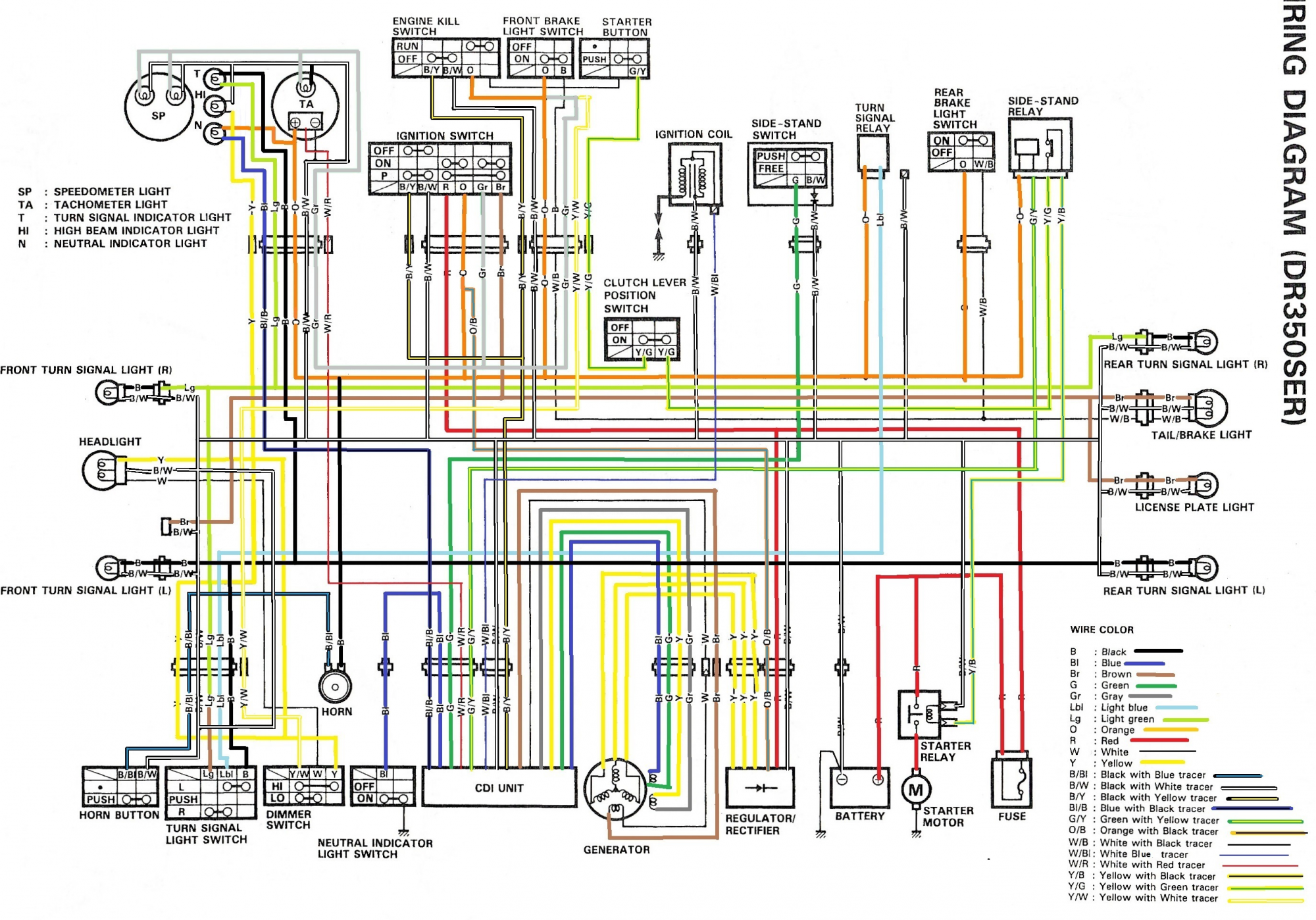
Wiring Diagram For A 1994 1400 Suzuki Intruder Vs Pics Wiring Collection
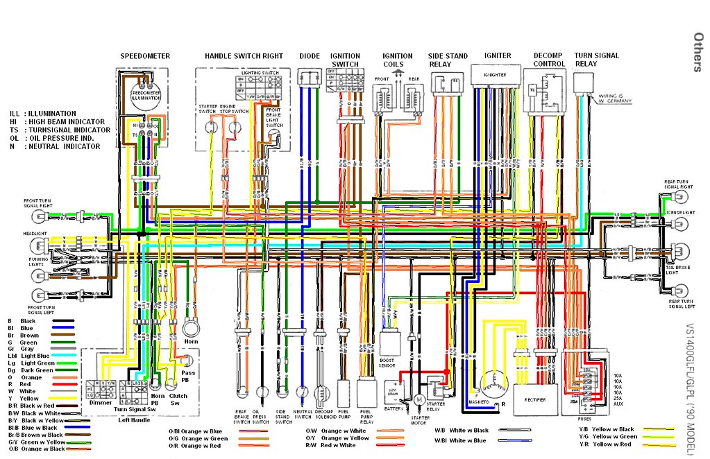
VS 1400 Wiring Diagram This is a colored wiring diagram fo… Flickr
Wiring Diagram For Schematic Wiring Diagrams


A Wiring Diagram Vs Schematic 15
Electrical Wiring Diagram Vs Schematic Cleaver KLT, Wiring Diagram With AC Generator, Contact

Wiring Diagram Vs Commodore Ac Home Wiring Diagram


Need Help with pin out for VS V8 Series two 1996 Just Commodores

Schematic Vs Wiring Diagram
View topic VS V8 PCM Wiring Diagram

Holden Wiring Diagram schematic and wiring diagram

View topic VS V6 Wiring Diagram Electrical problems, Automotive repair, Diagram
Vs V6 Commodore Ecu Wiring Diagram Wiring Diagram


wiring What's a schematic to other diagrams)? Electrical Engineering Stack Exchange

Vs Commodore Wiring Diagram Pdf
Wiring Diagram Vs Actual Wiring?? HVAC DIY Chatroom Home Improvement Forum

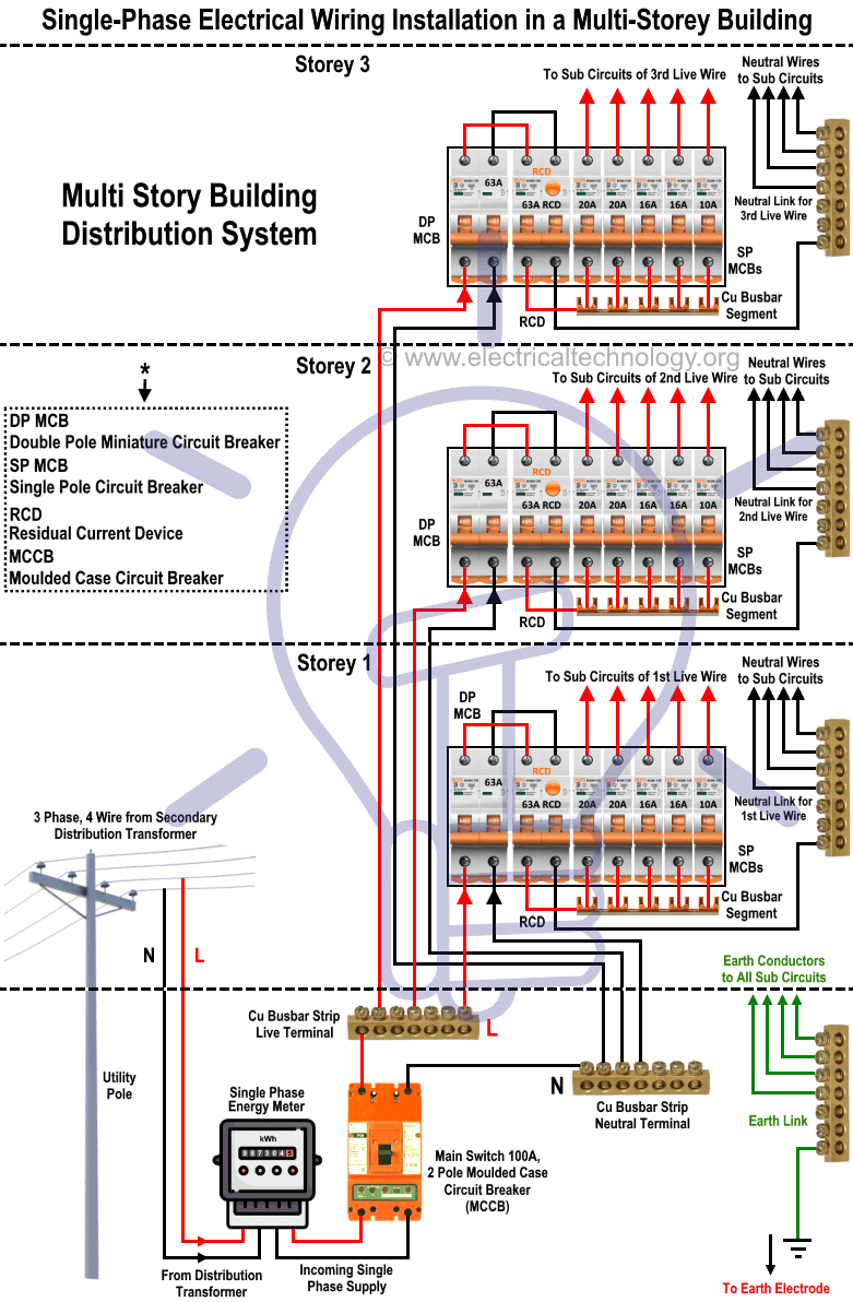
3 Phase To Single Phase Wiring Diagram Cadician's Blog
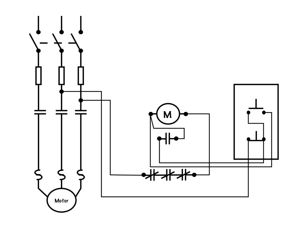
Schematic vs. Wiring Diagrams Basic Motor Control